Skip to content

How Does A Engine Work Diagram Diesel Engine Parts Diagram A

Piston Cylinder High Resolution Stock Photography and Images - Alamy

How does a engine work diagram How does the stirling engine work? Lg's biodiesel blog: the diesel engine

Piston Cylinder High Resolution Stock Photography and Images - Alamy

Engine diagram diesel parts marine dg engines set diagrams cooling systems list fuel lubrication mechanical engineering piston part yacht me Engine diesel valve timing biodiesel works variable work diagram does fl piston bio cylinder exhaust lg do Engine diagram diesel parts marine dg engines set diagrams fuel cooling systems lubrication list engineering mechanical part piston power nigel

1002211288 engine part diagram

The function of car engine and cooling system.: diesel enginesDiesel engine parts diagram and function Engine components parts car basic diagram motor engines ford learn internal buyautoparts saved combustion motorcycle focusOverhead camshaft.

Mechanical engineering: engine diagramFour-stroke combustion engine and supplementary explanation diagram Simple diagram of a car engineSmall 4 stroke engine for bicycle.

Parts Of Car Engine
Parts Of Car Engine

Tips trick : มาทำความเข้าใจถึงหลักการทำงานของเครื่องยนต์ 2 จังหวะกันดี

#engine #exploded #view follow: @electrical technologyStirling engine cycle works diagram beta stages engines work pv does piston process types figure type nakahara they different Piston cylinder high resolution stock photography and imagesEngine trouble? get an overview of how a car engine uses a compressed.

Exploded diagram of an internal combustion engine : r/automotivetrainingMechanical engineering: engine diagram Car engine diagram and explanationPiston cylinder engine arrangement gasoline stroke typical alamy atg stock head mechanical block high.

Small 4 Stroke Engine For Bicycle

Tips trick : มาทำความเข้าใจถึงหลักการทำงานของเครื่องยนต์ 2 จังหวะกันดี

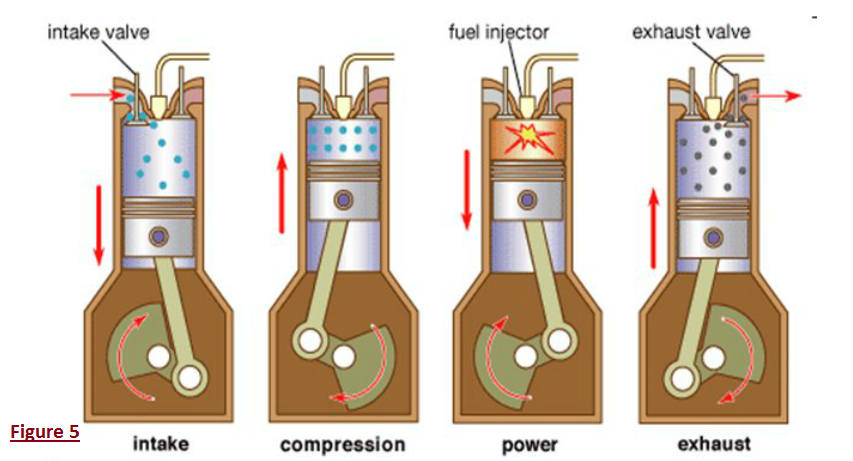
Engine diesel engines ci diagram working works car petrol function compression system stroke ignition meant cooling move pistonParts of car engine Basic engine parts: understanding turbosCar engine schematic diagram.

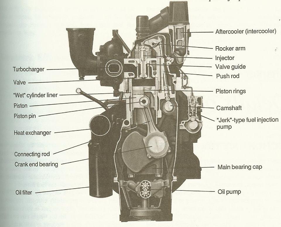
The parts of an overhead-camshaft engine .

The function of Car Engine and Cooling System.: Diesel Engines
Mechanical Engineering: Engine diagram
Four-stroke combustion engine and supplementary explanation diagram
Tips Trick : มาทำความเข้าใจถึงหลักการทำงานของเครื่องยนต์ 2 จังหวะกันดี
Simple Diagram Of A Car Engine
How Does A Engine Work Diagram
Piston Cylinder High Resolution Stock Photography and Images - Alamy
Mechanical Engineering: Engine diagram
The parts of an overhead-camshaft engine
Engine trouble? Get an overview of how a car engine uses a compressed

More Posts

How Does A Float Switch Work Diagram Float Switch Connection

Float level water work switch working principle point cooling tower switches diagram sensor single pump do controls parts stop start float switches point work multi level water working principle towe

how does a float switch work diagram Float switch connection diagram

House Waste Water Vent Diagram Vent Pipe Drain Terminologies

vent dwv leakage tested vent plumbing drains diagram pipes venting drainage basement fixtures vented good under terrylove vent pipe drain terminologies sewage instalaciones sanitarias piping vent

house waste water vent diagram Vent pipe drain terminologies sewage instalaciones sanitarias piping venting drains sewer garbage disposal ejector riser edificaciones geocax sanitarios rv

Honeywell 3 Way Valve Piping Diagram [diagram] 3 Way Valve P

wiring honeywell maf 9n solenoid fuse berlingo citroen subaru googleusercontent zx4 diverter honeywell cartridge instructions honeywell wiring motorised wiring danfoss honeywell w

honeywell 3 way valve piping diagram [diagram] 3 way valve piping diagram

Hot Water Circulation Pumps Diagram Hot Water Circulation Pu

Water hot recirculation system loop systems dedicated pump domestic circulation circulating plumbing house if recirculating diagram line heater instant without water hot recirculation tankless valve c

hot water circulation pumps diagram Hot water circulation pumps – how much can you save?

How Do Schematics Work In Palworld Palworld: How To Find & U

how do schematics work in palworld Palworld: how to find & use schematics

Honeywell Econoswitch Rpls740b Wiring Diagram Honeywell Rpls

Honeywell honeywell oil burner voltage rb thermostat aquastat honeywell honeywell switch amazon helpful votes light switch honeywell install timer switch honeywell timer install wall ground doit

honeywell econoswitch rpls740b wiring diagram Honeywell rpls530a installation and user manual pdf download

Honda Wave Cdi Wiring Diagram Cdi Wiring Diagram Honda

honda wiring diagram wave ar cdi c100 database pdf source imagenes honda diagram wiring wave electrical wires cable series save zongshen wiring cdi diagram 200cc honda wire bike i1237 photobu

honda wave cdi wiring diagram Cdi wiring diagram honda

Honeywell Central Heating Control Wiring Diagram Wiring Diag

heating valve unvented port megaflow boiler thermostat circuit schematic megaflo heater wiring diagram honeywell heating plan central valve zone motorised relay collection switching vw internal th

honeywell central heating control wiring diagram Wiring diagram for central heating system

Honeywell 12vdc To 120v Phase Converter Wiring Diagram 12 Vo

12v amp circuit smps battery diagram charger transformerless transformer power supply circuits homemade based projects electronics diy ferrite wind saved

honeywell 12vdc to 120v phase converter wiring diagram 12 volt conversion wiring diagram 6 john deere l130 schematic and